3D printing for industrial purposes
Learn about the advantages and disadvantages of various methods of industrial 3D printing, materials that are commonly used, and more
Read articleIn this introduction to Binder Jetting 3D printing, we cover the basic principles of the technology. After reading this article you will understand the fundamental mechanics of the Binder Jetting process and how these relate to its benefits and limitations.
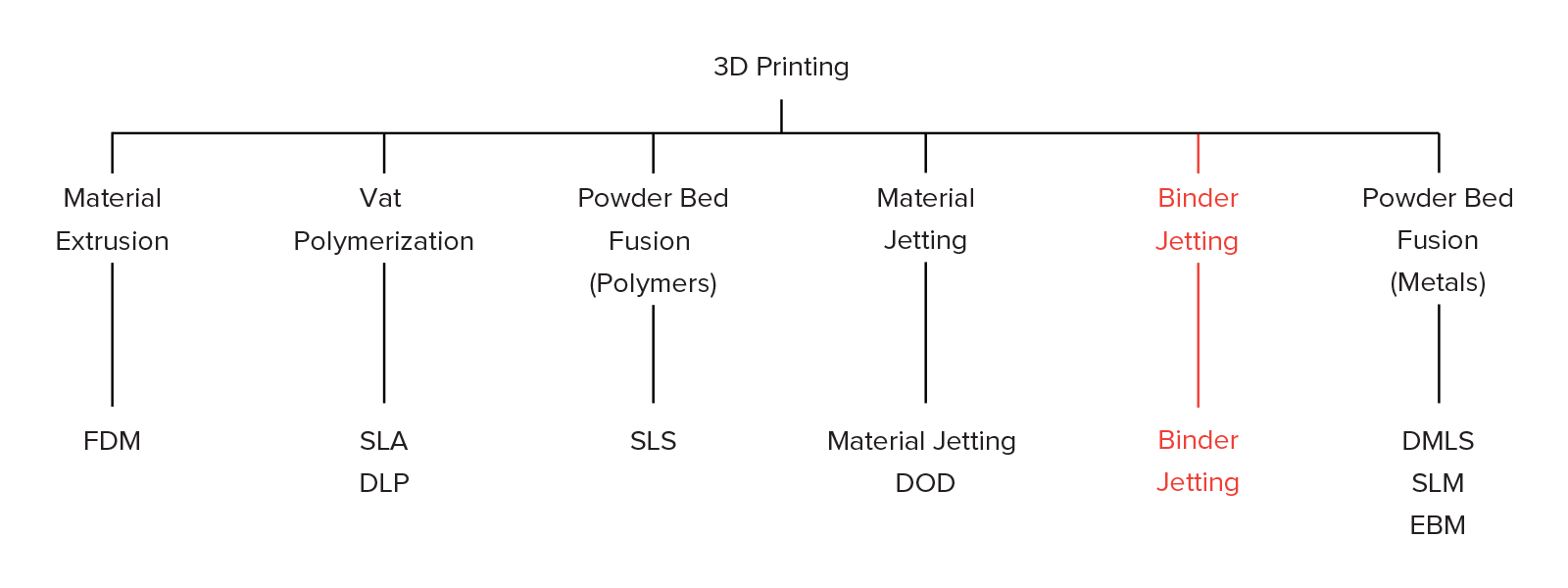
Binder Jetting is a family of additive manufacturing processes. In Binder Jetting, a binder is selectively deposited onto a powder bed, bonding these areas together to form a solid part one layer at a time. The materials commonly used in Binder Jetting are metals, sand, and ceramics that come in a granular form.
Binder Jetting is used in various applications, including the fabrication of full-color prototypes (such as figurines), the production of large sand casting cores and molds and the manufacture of low-cost 3D printed metal parts.
With such diverse applications, it is essential for a designer who wants to use the capabilities of Binder Jetting to the fullest, to understand the basic mechanics of the process and how these connect to its key benefits and limitations.
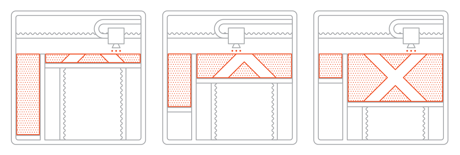
Here is how the Binder Jetting process works:
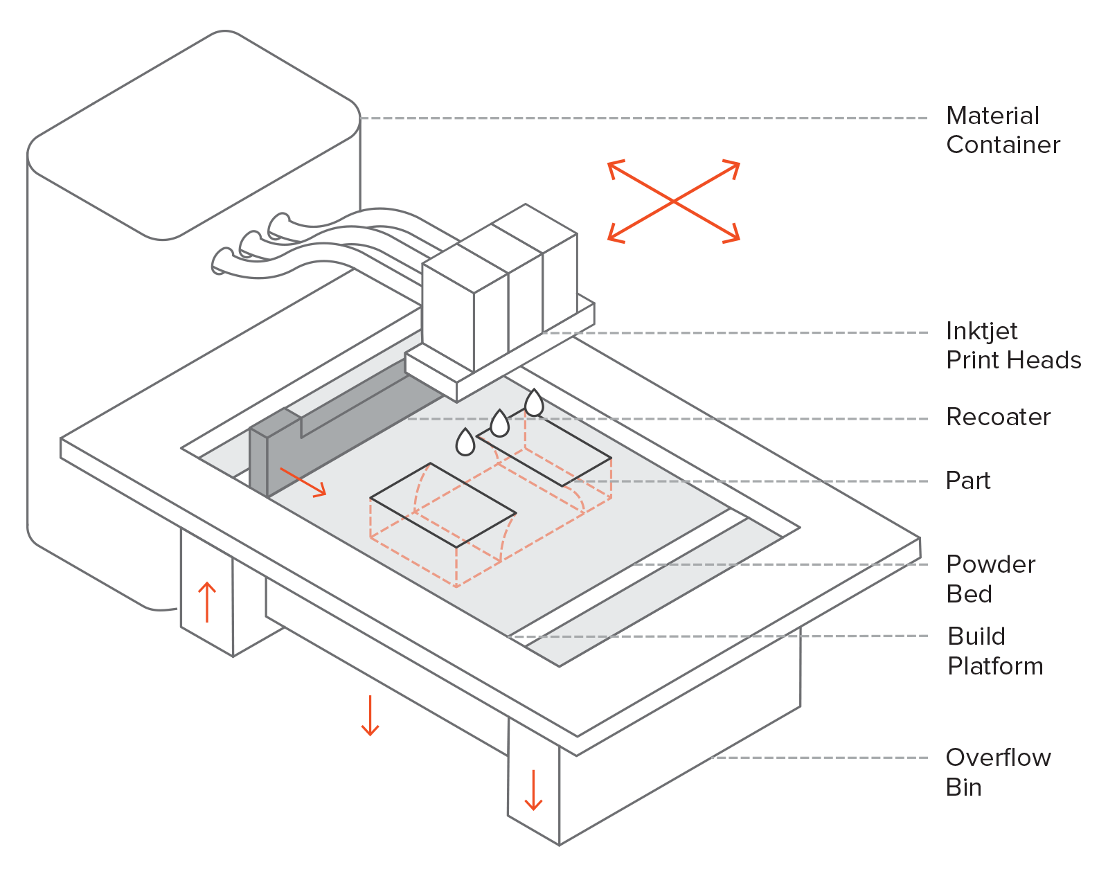
I. First, a recoating blade spreads a thin layer of powder over the build platform.
II. Then, a carriage with inkjet nozzles (which are similar to the nozzles used in desktop 2D printers) passes over the bed, selectively depositing droplets of a binding agent (glue) that bond the powder particles together. In full-color Binder Jetting, the colored ink is also deposited during this step. The size of each drop is approximately 80 μm in diameter, so good resolution can be achieved.
III. When the layer is complete, the build platform moves downwards and the blade re-coats the surface. The process then repeats until the whole part is complete.
IV. After printing, the part is encapsulated in the powder and is left to cure and gain strength. Then the part is removed from the powder bin and the unbound, excess powder is cleaned via pressurized air.
Depending on the material, a post-processing step is usually required. For example, metal Binder Jetting parts need to be sintered (or otherwise heat treated) or infiltrated with a low-melting-temperature metal (typically bronze). Full-color prototypes are also infiltrated with acrylic and coated to improve the vibrancy of colors. Sand casting cores and molds are typically ready to use after 3D printing.
This is because the parts are in a “green” state when they leave the printer. Binder Jetting parts in the green state have poor mechanical properties (they are very brittle) and high porosity.
In Binder Jetting, almost all process parameters are preset by the machine manufacturer.
The typical layer height depends on the material: for full color models the typical layer height is 100 microns, for metal parts 50 microns and for sand casting mold materials 200-400 microns.
A key advantage of Binder Jetting over other 3D printing processes is that bonding occurs at room temperature. This means that dimensional distortions connected to thermal effects (such as warping in FDM, SLS, DMSL/SLM or curling in SLA/DLP) are not a problem in Binder Jetting.
As a result, the build volume of Binder Jetting machines are amongst the largest compared to all 3D printing technologies (up to 2200 x 1200 x 600 mm). These large machines are generally used to produce sand casting molds. Metal Binder Jetting systems typically have larger build volumes than DMSL/SLM systems (up to 800 x 500 x 400 mm), which allows the parallel manufacturing of multiple parts at a time. The maximum part size though is restricted to a recommended length of up to 50 mm, due to the post-processing step involved.
Moreover, Binder Jetting requires no support structures: the surrounding powder provides to the part all the necessary support (similar to SLS). This is a key difference between metal Binder Jetting and other metal 3D printing processes, which usually require extensive use of support structures, and allows for the creation of freeform metal structures with very few geometric restrictions. Geometric inaccuracies in metal Binder Jetting come mainly from the post-processing steps, as discussed in a later section.
Since the parts in Binder Jetting do not need to be attached to the build platform, the whole build volume can be utilized. Thus, Binder Jetting is suitable for low-to-medium batch production. To take advantage of the full capabilities of Binder Jetting, it is very important to consider how to fill effectively the whole build volume of the machine (bin packing).
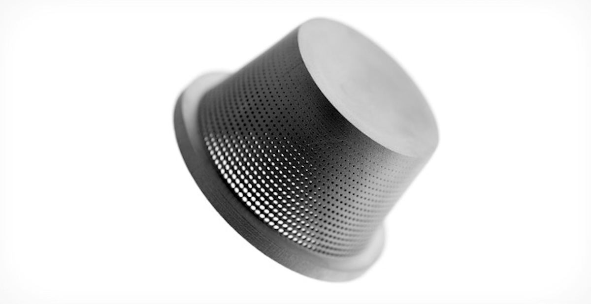
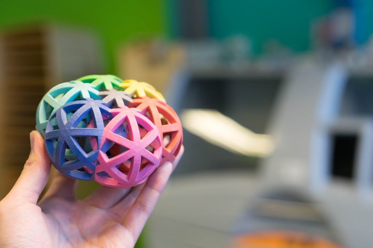
Binder Jetting can produce full color 3D printed parts in a similar way to Material Jetting. It is often used to 3D print figurines and topographical maps, because of its low cost.
Full-color models are printed using sandstone powder or PMMA powder. The main printhead first jets the binding agent, while a secondary print head jets a colored ink. Inks with different colors can be combined to produce a very large array of colors, in a similar way to a 2D inkjet printer.
After printing, the parts are then coated with cyanoacrylate (super glue) or a different infiltrant to improve part strength and enhance the vibrancy of the colors. A secondary epoxy layer can then also be added to further improve strength and color appearance. Even with these extra steps, full-color Binder Jetting parts are very brittle and they are not recommended for functional applications.
To produce full-color prints, a CAD model that contains the color information must be provided. Color can be applied to CAD models via two methods: on a per face approach or as a texture map. Applying color on a per face basis is quick and easy to implement, but using a texture map allows for more controls and greater detail. Refer to your native CAD software for specific instructions.
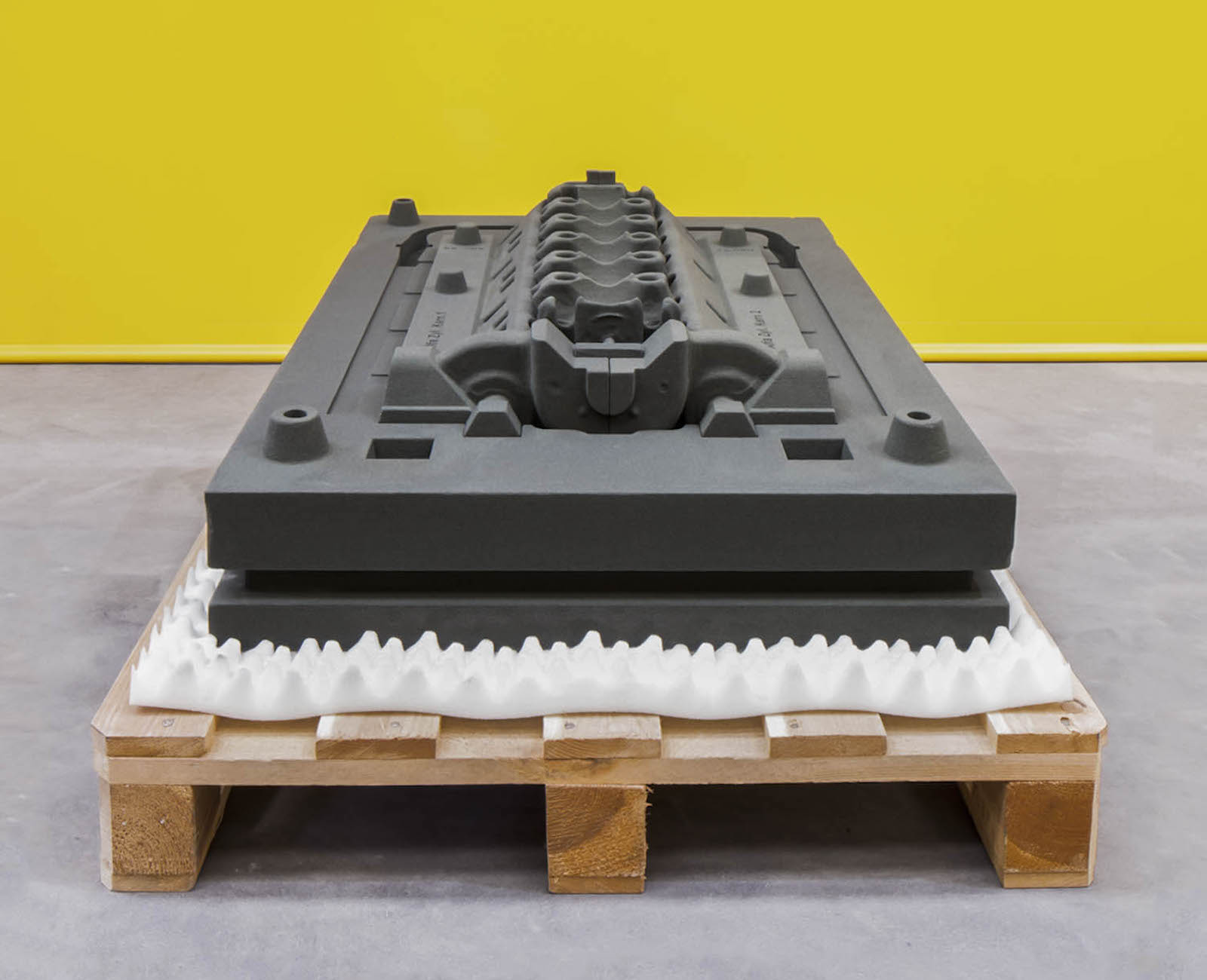
The production of large sand casting patterns is one of the most common uses for Binder Jetting. The low cost and speed of the process make it an excellent solution for elaborate pattern designs that would be very difficult or impossible to produce using traditional techniques.
The cores and molds are generally printed with sand or silica. After printing, the molds are generally immediately ready for casting. The casted metal component is usually removed from them after casting by breaking the mold. Even though these molds are used only once, the time and cost savings compared to traditional manufacturing are substantial.
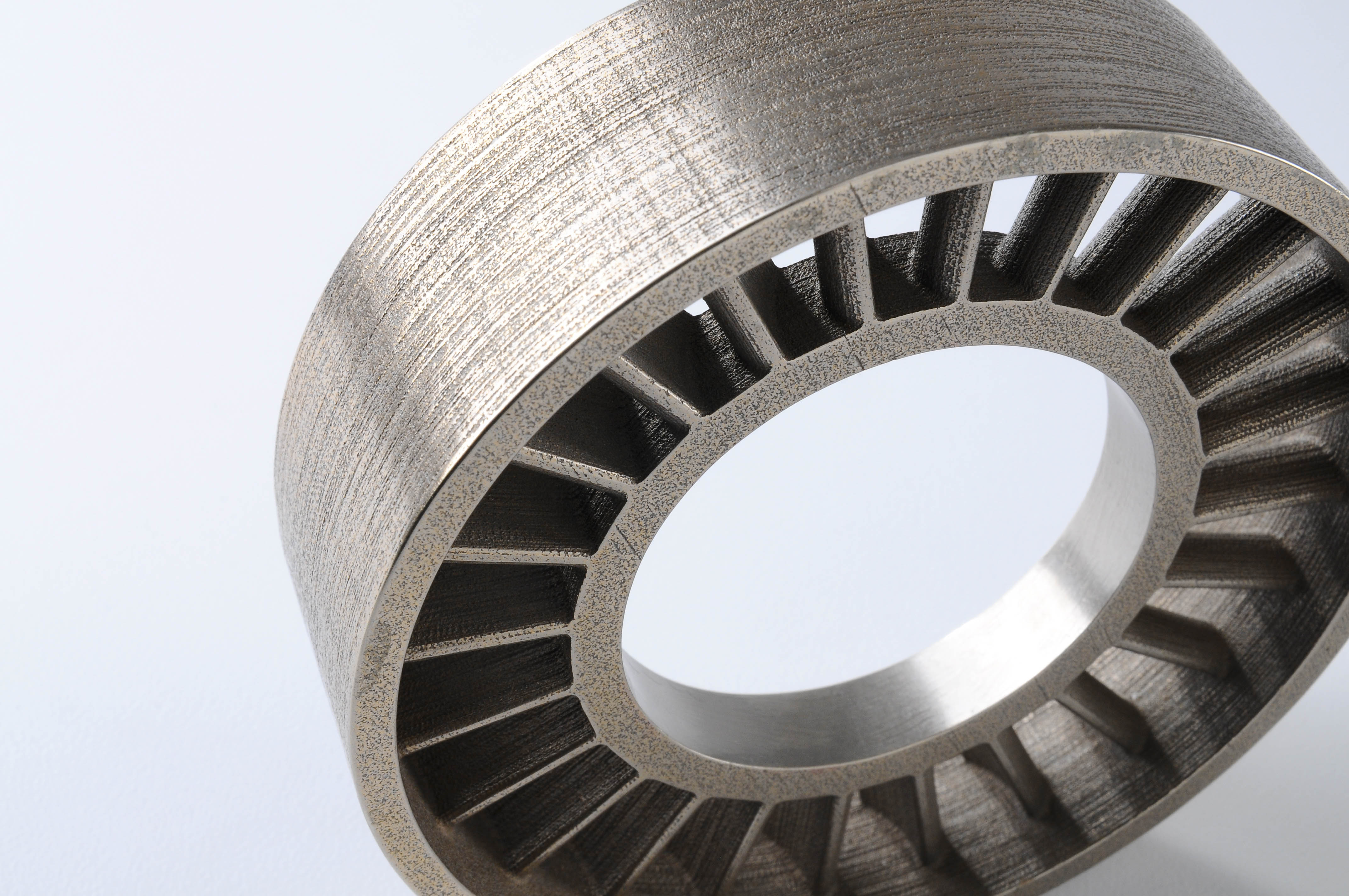
Metal Binder Jetting is up to 10x more economical than other metal 3D printing processes (DMSL/SLM). Moreover, the build size of Binder Jetting is considerably large and the produced parts require no support structures during printing, enabling the creation of complex geometries. This makes metal Binder Jetting a very appealing technology for low-to-medium metal production.
The main drawback of metal Binder Jetting parts are their mechanical properties, which are not suitable for high-end applications. Nevertheless, the material properties of the produced parts are equivalent to metal parts produced with Metal Injection Molding, which is one of the most widely used manufacturing methods for the mass production of metal parts.
Metal Binder Jetting parts require a secondary process after printing, like infiltration or sintering, to achieve their good mechanical properties, as the as-printed parts basically consist of metal particles bound together with a polymer adhesive.
Infiltration: After printing, the part is placed in a furnace, where the binder is burnt out leaving voids. At this point, the part is approximately 60% porous. Bronze is then used to infiltrate the voids via capillary action, resulting in parts with low porosity and good strength.
Sintering: After printing is complete, the parts are placed in a high temperature furnace, where the binder is burnt out and the remaining metal particles are sintered (bonded) together, resulting in parts with very low porosity.
Accuracy and tolerance can vary greatly depending on the model and are hard to predict as they are greatly dependant on the geometry. For example, parts with length up to 25 - 75 mm shrink between 0.8 to 2% after infiltration, while larger parts have an estimated average shrinkage of 3%. For sintering, the part shrinkage is approximately 20%. The dimensions of the parts are compensated for shrinkage by the machine’s software, but non-uniform shrinkage can be an issue and must be accounted for during the design stage in collaboration with the Binder Jetting machine operator.
The post-processing step can also be the source of inaccuracies. For example, during sintering, the part is heated to a high temperature and becomes softer. In this softer state, unsupported areas might deform under their own weight. Moreover, as the part shrinks during sintering, there here is friction between the plate of the furnace and the lower surface of the part, which may lead to warping. Again, communication with the Binder Jetting machine operator is key here to ensure optimal results.
Sintered or infiltrated Binder Jetting metal parts will have an internal porosity (sintering produces 97% dense parts, while infiltration approximately 90%). This affects the mechanical properties of metal Binder Jetting parts, as the voids can lead to crack initiation. Fatigue and fracture strength and elongation at break are the material properties that are most affected by internal porosity. Advanced metallurgical processes (like Hot isostatic pressing or HIP) can be applied to produce parts with almost no internal porosity. For applications where mechanical performance is critical though, DMLS or SLM are the recommended solutions.
An advantage of metal Binder Jetting compared to DMLS/SLM, is the surface roughness of the produced parts. Typically, metal Binder Jetted parts have a surface roughness of Ra 6 μm after post-processing, which can be reduced to Ra 3 μm if a bead-blasting step is employed. In comparison, the as-printed surface roughness of DMLS/SLM parts is approximately Ra 12-16 μm. This is particularly beneficial for parts with internal geometries, for example internal channels, where post-processing is difficult.
The table below summarizes the differences in the main mechanical properties of Stainless Steel parts, printed with Binder Jetting and DMLS/SLM:
| Binder Jetting Stainless Steel 316 (sintered) | Binder Jetting Stainless Steel 316 (bronze infiltrated) | DMLS/SLM Stainless Steel 316L | |
|---|---|---|---|
| Yield Strength | 214 MPa | 283 MPa | 470 MPa |
| Elongation at Break | 34% | 14.5% | 40% |
| Modulus of Elasticity | 165 GPa | 135 GPa | 180 GPa |
Binder Jetting powders come in range of materials. The final application of the part defines the most appropriate powder. The cost of the ceramic powders is usually low. Metal powders are more expensive, yet more economical than DMSL/SLM materials. Unlike the SLS 3D printing process, 100% of the unbonded powder can be recycled, leading to more material savings.
| Material | Characteristics |
|---|---|
| Full Color Sandstone |
Full colour non-functional models
Very brittle
|
| Silica Sand |
Very high thermal resistance
Excellent for sand casting applications
|
| Stainless steel (bronze infiltrated) |
Good mechanical properties
Can be machined
~10% internal porosity
|
| Stainless steel (sintered) |
Very good mechanical properties
High corrosion resistance
~3% internal porosity
|
| Inconel alloy (sintered) |
Excellent mechanical properties
Good temperature resistance
High chemical resistance
|
| Tungsten carbide (sintered) |
Very high hardness
Used for the production of cutting tools
|
The key advantages and disadvantages of the technology are summarised below:
The main characteristics of Binder Jetting are summarized in the table below:
| Binder Jetting | |
|---|---|
| Materials | Metals, Ceramics (sand) |
| Dimensional accuracy | Metal: ± 2% or 0.2 mm (down to ± 0.5% or ± 0.05) Full-color: ± 0.3 mm Sand: ± 0.3 mm |
| Typical build size | Metal: 400 x 250 x 250 mm (up to 800 x 500 x 400 mm) Full-color: 200 x 250 x 200 mm (up to 500 x 380 x 230 mm) Sand: 800 x 500 x 400 (up to 2200 x 1200 x 600 mm) |
| Common layer thickness | Metal: 35 - 50 μm Full-color: 100 μm Sand: 200 - 400 μm |
| Support | Not required |